API Plan

API Plan

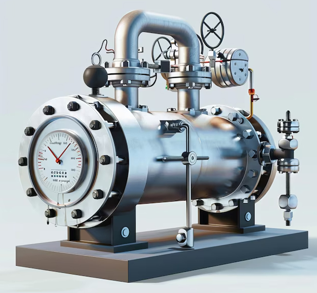
API (American Petroleum Institute) Seal Plans are standardized piping arrangements developed to enhance the performance, reliability, and efficiency of mechanical seals used in pumps and other rotating equipment. These plans play a crucial role in managing seal chamber pressure, maintaining proper lubrication, dissipating heat, and preventing contamination, all of which contribute to the longevity and efficiency of mechanical seals. By implementing the appropriate API plan, industries can significantly reduce downtime, maintenance costs, and the risk of equipment failure due to seal degradation. API seal plans are categorized into different configurations based on single or dual seals, process fluid circulation, and external support systems such as quenching, buffer or barrier fluid pressurization, and dry gas sealing. Single seal flush plans, such as API Plan 11, 13, and 23, utilize process fluids for lubrication and cooling by redirecting them through the seal chamber. Dual seal plans, including API Plan 52 and 53A/B/C, use buffer or barrier fluids to prevent leakage and enhance seal protection.

Types Of API Plan

API Plan 21
refers to a mechanical seal flush plan where fluid from the pump discharge is recirculated through a flow control orifice and a cooler before being directed back into the seal chamber, essentially providing a cooled flush fluid to the process side of the seal, ideal for high temperature applications where cooling is needed to maintain proper seal lubrication and prevent coking or polymerization; it is considered a self-venting plan and is particularly useful for fluids with low vapor pressure margins.
Function Recirculates pump discharge fluid through a cooler to provide cooled flush fluid to the seal chamber.
Benefits
  • Improves temperature margin
  • Reduces coking
  • Enhances lubricity
  • Suitable for high temperature applications
Components Flow control orifice, heat exchanger/cooler, piping to route fluid from discharge to seal chamber.
Application Used for hot non-polymerizing fluids with low vapor pressure margin.
API Plan 23
API Plan 23 refers to a piping plan within the American Petroleum Institute (API) standards, specifically designed for mechanical seals, where fluid from the seal chamber is recirculated through a cooler and back to the chamber, effectively cooling the seal faces by creating a closed loop system, typically utilizing a pumping ring to maintain circulation; this is commonly used in applications with hot process fluids like boiler feed water or hot hydrocarbons to prevent vaporization and maintain seal integrity.
Function To cool the mechanical seal faces by circulating the fluid from the seal chamber through a heat exchanger and back to the chamber.
Circulation Method A pumping ring within the seal chamber is typically used to facilitate the fluid flow.
Benefits
  • Improves seal life by maintaining a cooler temperature at the seal faces
  • Reduces the risk of vaporization and coking
Applications Primarily used in hot process applications like boiler feed water or hot hydrocarbon services.
API Plan 32
Plan 32 refers to a piping plan used in mechanical seals where a clean, external fluid is injected directly into the seal chamber to isolate the process fluid from the seal faces, typically employed when the process fluid is contaminated, dirty, or unsuitable for use as a flush fluid, effectively creating a clean environment for the seal to operate in; it often utilizes a close-clearance throat bushing to maintain a higher pressure within the seal chamber and prevent process fluid from entering.
Function Delivers a clean flush fluid from an external source into the seal chamber.
Application Used when the process fluid is contaminated, contains solids, has poor lubrication properties, or is at high temperatures.
Components Typically includes a close-clearance throat bushing to separate the process fluid from the flush fluid.
Benefits Improves seal life by providing a clean environment for the seal faces.
Additional Application Note Often utilizes a close-clearance throat bushing to ensure the flush fluid effectively reaches the seal faces while minimizing contamination from the process fluid.
API Plan 52
API Plan 52 refers to a mechanical seal support system that utilizes an external reservoir to circulate a low-pressure "buffer fluid" between the inner and outer seals of a dual seal arrangement, effectively preventing process fluid contamination while providing cooling and lubrication to the seals, typically used for applications with light hydrocarbons or high vapor pressure fluids where direct process leakage to atmosphere needs to be minimized; it is considered a low-pressure containment system for non-hazardous fluids.
Function Circulates an unpressurized buffer fluid from an external reservoir between the seals to prevent process fluid leakage and provide cooling.
Application Primarily used with dual unpressurized mechanical seals.
Benefits
  • No process fluid contamination
  • Near-zero process emissions
  • Heat removal from the inboard seal
  • Acts as a secondary seal to prevent leakage to atmosphere
Important Considerations
  • Pressure limitations: Buffer fluid is maintained at a pressure lower than the seal chamber pressure.
  • Not for high-pressure applications: Unsuitable for highly pressurized or hazardous fluids.
  • Maintenance needs: Regular monitoring of buffer fluid level and quality is required.
API Plan 53A
API Plan 53A refers to a standardized system used in mechanical seals, where a pressurized barrier fluid is circulated between the inboard and outboard seals of a dual seal arrangement, ensuring that any leakage from the primary seal is contained by a pressurized barrier fluid that is maintained at a pressure higher than the process fluid pressure, preventing leakage to the atmosphere and providing optimal seal performance; typically utilizing an external nitrogen source to pressurize the barrier fluid reservoir.
Function Maintains a clean, pressurized barrier fluid between the seal faces to prevent process fluid leakage and extend seal life.
Pressure Source A pressurized gas like nitrogen is used to maintain pressure in the barrier fluid reservoir, usually set higher than the process pressure.
Application Used when no process fluid leakage to the atmosphere can be tolerated, such as with hazardous or toxic media.
Important Consideration The barrier fluid must be compatible with the process fluid as some leakage of the barrier fluid into the product is expected.
Components
  • Reservoir: Stores the pressurized barrier fluid
  • Cooling coil (optional): Maintains the barrier fluid temperature
  • Pumping ring: Facilitates circulation of the barrier fluid
API Plan 53B
API Plan 53B is a mechanical seal support system that utilizes a pressurized barrier fluid circulated between the inboard and outboard seals of a dual seal arrangement, maintaining pressure through a bladder accumulator, which separates the pressurizing gas from the barrier fluid, allowing for high-pressure applications where the process media is unsuitable for lubricating the inner seal faces; essentially, it provides a clean, pressurized fluid barrier to prevent leakage and extend seal life, particularly in harsh conditions.
Bladder Accumulator The primary feature is a bladder accumulator which stores pressurized gas (like nitrogen) to maintain a constant barrier fluid pressure without direct contact between the gas and the barrier liquid.
High-Pressure Capability This plan is designed to handle higher barrier pressures compared to other plans like 53A, making it suitable for high-pressure applications.
Barrier Fluid Circulation The barrier fluid is continuously circulated through the seal chamber and a cooler to remove heat generated by friction.
Applications Used when the process media is incompatible with the inner seal faces, contains abrasives, or is considered hazardous, requiring a clean barrier fluid.
Important Considerations
  • Barrier fluid compatibility: Ensure the barrier fluid is compatible with the process fluid to avoid contamination if leakage occurs.
  • Heat removal: Proper cooler design is crucial to maintain the barrier fluid temperature within acceptable limits.
  • Pressure monitoring: Regularly monitor the barrier fluid pressure to detect potential leaks and ensure adequate pressure maintenance.
API Plan 62
API Plan 62 refers to a piping plan used in mechanical seal systems where an external "quench" fluid, like steam, water, or nitrogen, is directed to the atmospheric side of a single seal to cool the seal faces, prevent material buildup, and control temperature, particularly in applications with hot or reactive fluids like hydrocarbons where coking could occur; essentially acting as a barrier between the process fluid and the atmosphere by flushing away unwanted substances on the seal faces.
Function Provides a quench fluid to the atmospheric side of the seal to cool it and prevent contamination or crystallization.
Application Used in situations where hot hydrocarbons, caustic fluids, or other materials prone to coking or crystallization are present.
Common Quench Fluids Steam (to prevent coking), nitrogen (for cryogenic applications), or clean water.
Important Considerations Requires a throttle bushing to direct the quench fluid precisely to the seal faces and ensure proper pressure control.
API Plan 74
API Plan 74 refers to a piping arrangement within the API 682 standard, where a clean, pressurized barrier gas (typically nitrogen) is externally supplied to a dual mechanical seal system, ensuring that even if a primary seal fails, no process fluid leaks to the atmosphere, making it ideal for applications with hazardous or toxic fluids where leakage cannot be tolerated; it essentially provides a "buffer" of clean gas between the seals to prevent contamination.
Function Uses a pressurized barrier gas, usually nitrogen, to maintain a positive pressure differential between the seal faces, preventing process fluid from escaping.
Application Primarily used in situations where the process fluid is hazardous or toxic, and even slight leakage could be dangerous.
Seal Configuration Typically used with "Arrangement 3" dual pressurized non-contacting gas seals.
Control Panel A dedicated control panel regulates the pressure and filters the barrier gas to ensure cleanliness.
Benefits
  • High reliability due to the constant supply of clean barrier gas
  • Minimal process fluid leakage to the environment
  • Suitable for applications with moderate temperatures and poor lubrication properties